Dome light switch

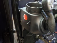
My switches are mounted in the plastic on the side just below the cupholders.


Dave
Hey Dave, what final route did you take to get the wires run back up to the light? I saw earlier where you had run them behind the window seal, but you had an ingress of water after that. Did you get your leak sealed? I don't mind drilling into plastic, as it is not needed for structural integrity. Routing the wiring around all the glass in our units looks like it would be tough.
 
Hey Dave, what final route did you take to get the wires run back up to the light? I saw earlier where you had run them behind the window seal, but you had an ingress of water after that. Did you get your leak sealed? I don't mind drilling into plastic, as it is not needed for structural integrity. Routing the wiring around all the glass in our units looks like it would be tough.


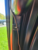
The windshield has the gasket on it and it's mounted with hinges at the top and brackets at the bottom so it sandwiches the gasket to A pillar. When I was tucking the wires between the gasket and A pillar I actually pushed them all the way so they were sticking out in a few places and that's where the water came in. I temporarily used those sticky bases that you can zip tie to, but they are a little janky looking. My plan is to tuck them back under the gasket but I'll pay more attention to WTF I'm doing.

Dave
 

Attachments

  • 20230927_143822.jpg
    20230927_143822.jpg
    1.1 MB · Views: 1
My wireless remote option is supposed to be here on Friday. If it actually shows up, I will install it Saturday and then post back on any difficulties installing it, pictures and then a write up about distance it works and if I have plans on doing anything different and upgrading to a module that has more than one controllable output. I live very rural, back in the middle of my woods. It is darker than coal at night under the carport and I currently have to feel my way around to find the light dome switch. I did it that way for 12 years with my Gator at night. It didn't have a dome light. To see at night, I had to find the ignition switch, insert the key in the right direction, start the gator and then fumble with 4 different switches on the dash to find the headlight switch. I can't wait to enter the 21st century....lol.
 
Ok, this will be a long one. Lots of pictures taken that need to be posted for the tutorial. Not sure how large a post can be? If it gets too big or it needs it's own thread, I am good with that.

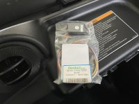
My parts for the remote control domelight project came in today. Like a kid on Xmas morning (you guys know you still get giddy when UPS or FedEX shows up), I rushed to the mailbox and retrieved my package. Huh.....was kind of expecting a box, but, oh well. I tear open the soft side package and remove the clear plastic bag. This is what came with the kit:

IMG_9518.JPG

IMG_9519.JPG

A little plastic project box with 5 colored wires coming out of it, a little Keychain FOB with ON and OFF push buttons, a spare A27 12VDC alkaline battery and a folded up piece of paper, which I am assuming is the high tech directions. Everything looked good and nothing was damaged in shipment.

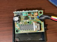
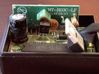
I open the package and take out the contents. Now, I am one of those children that always took their toys apart to see how they worked. So, yep, I am gonna take the cover off the magic black box, just to peek inside and see what makes this thing tick.

IMG_9521.JPG

IMG_9523.JPG

IMG_9524.JPG


IMG_9525.JPG


IMG_9526.JPG


Not really much to it. 5- #20 gauge colored wires, with individual labels on them, a small RF receiver board, a filter cap, a diode or two, etc.

IMG_9528.JPG

So, I grab all the tools and pieces I need and walk to the RTV-X1100C sitting out in the car port. The first thing I am going to do is remove the cover for where a radio would go. Very easy.

IMG_9514.JPG

IMG_9517.JPG


The area circled in red viewed through the radio opening is where the dome light is at and its electrical connector. The cover for the domelight just under this opening will have to be popped off to get to the two #2 Phillips head screws holding it onto the head liner.


The automated Admin just told me I can only attach 10 pics. I will start a new post for the rest of the story.
 
Ok, this will be a long one. Lots of pictures taken that need to be posted for the tutorial. Not sure how large a post can be? If it gets too big or it needs it's own thread, I am good with that.

My parts for the remote control domelight project came in today. Like a kid on Xmas morning (you guys know you still get giddy when UPS or FedEX shows up), I rushed to the mailbox and retrieved my package. Huh.....was kind of expecting a box, but, oh well. I tear open the soft side package and remove the clear plastic bag. This is what came with the kit:

View attachment 14901

View attachment 14902

A little plastic project box with 5 colored wires coming out of it, a little Keychain FOB with ON and OFF push buttons, a spare A27 12VDC alkaline battery and a folded up piece of paper, which I am assuming is the high tech directions. Everything looked good and nothing was damaged in shipment.

I open the package and take out the contents. Now, I am one of those children that always took their toys apart to see how they worked. So, yep, I am gonna take the cover off the magic black box, just to peek inside and see what makes this thing tick.

View attachment 14903

View attachment 14904

View attachment 14905


View attachment 14906


View attachment 14907


Not really much to it. 5- #20 gauge colored wires, with individual labels on them, a small RF receiver board, a filter cap, a diode or two, etc.

View attachment 14908

So, I grab all the tools and pieces I need and walk to the RTV-X1100C sitting out in the car port. The first thing I am going to do is remove the cover for where a radio would go. Very easy.

View attachment 14909

View attachment 14910


The area circled in red viewed through the radio opening is where the dome light is at and its electrical connector. The cover for the domelight just under this opening will have to be popped off to get to the two #2 Phillips head screws holding it onto the head liner.


The automated Admin just told me I can only attach 10 pics. I will start a new post for the rest of the story.
Remove the little semi clear plastic cover on the dome light by pressing in the end closest to the on/off switch.

IMG_9543.JPG

IMG_9540.JPG

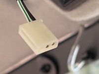
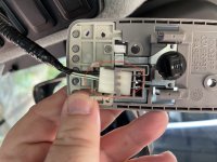
After carefully removing the two screws, gently pull straight down on the dome light body. The light will drop and the factory 2 wire connector will still be attached.

IMG_9533.JPG

Slide as much slack as you can on the loom covered wires and gently pull the connector, with the black and white/ green stripe wire straight out to the left. As a reference, black wire is ground and white/green stripe is 12VDC hot wire.

IMG_9534.JPG

Place the light fixture to the side for now. Next, we will remove the black electrical tape, holding the loom onto the wires. When the tape is removed, split the loom open and extract the two wires.

IMG_9529.JPG

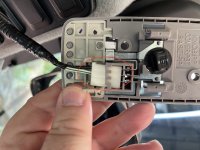
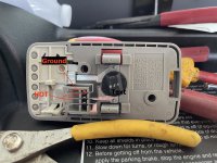
On the back of the light fixture are 3 pins. If orienting the dome light fixture like shown in the picture, the top pin is ground, the middle pin is +12VDC. You will need to remember this, as the solid state remote control module switches the light on and off by making and breaking the ground connection, not the +12VDC connection.

Next, we are going to start wiring the control module into the RTV's electrical circuit.

IMG_9532.JPG


Take your wire cutters and cut the black ground wire about 4 inches up from the plug. DO NOT CUT BOTH THE BLACK WIRE AND WHITE/GREEN STRIPE WIRE AT THE SAME TIME! Cutting both wires at the same time will cause a direct short and you will blow your 5A fuse immediately. After you have cut the black wire, then do the same for the white/green stripe wire. Now, you should have a white electrical connector with two 4" pigtails. Lay it to the side.

IMG_9536.JPG

You will strip back about 1/4" of insulation on all 4 of the colored wires on the remote control (except blue. Blue is just an antenna wire) Then you are going to strip back 1/4" of insulation on your wires on the plug, then the black wire coming from inside the radio cavity and last, very carefully strip back 1/4" of insulation on the white/green stripe wire coming from inside the radio cavity, pay very close attention that your strippers or the stripped black wire does not come into contact with each other. Now, you are ready to start butt splicing wires together. From the remote control module, butt splice the red wire to the white/green stripe wire coming from the radio cavity. Next, butt splice the black wire from the remote control module to the black wire coming from the radio cavity.

IMG_9537.JPG
Now, you are going to pickup your light dome fixture, spice the yellow wire from the remote control module onto the black pigtail wire. Last wire splice will be the white wire from the remote control module to the white/green stripe on the pigtail. The wiring of the module is now complete.

I'll open another post to finish this.
 

Attachments

  • IMG_9533.JPG
    IMG_9533.JPG
    2.3 MB · Views: 0
Remove the little semi clear plastic cover on the dome light by pressing in the end closest to the on/off switch.

View attachment 14911

View attachment 14912

After carefully removing the two screws, gently pull straight down on the dome light body. The light will drop and the factory 2 wire connector will still be attached.

View attachment 14913

Slide as much slack as you can on the loom covered wires and gently pull the connector, with the black and white/ green stripe wire straight out to the left. As a reference, black wire is ground and white/green stripe is 12VDC hot wire.

View attachment 14914

Place the light fixture to the side for now. Next, we will remove the black electrical tape, holding the loom onto the wires. When the tape is removed, split the loom open and extract the two wires.

View attachment 14915

On the back of the light fixture are 3 pins. If orienting the dome light fixture like shown in the picture, the top pin is ground, the middle pin is +12VDC. You will need to remember this, as the solid state remote control module switches the light on and off by making and breaking the ground connection, not the +12VDC connection.

Next, we are going to start wiring the control module into the RTV's electrical circuit.

View attachment 14917


Take your wire cutters and cut the black ground wire about 4 inches up from the plug. DO NOT CUT BOTH THE BLACK WIRE AND WHITE/GREEN STRIPE WIRE AT THE SAME TIME! Cutting both wires at the same time will cause a direct short and you will blow your 5A fuse immediately. After you have cut the black wire, then do the same for the white/green stripe wire. Now, you should have a white electrical connector with two 4" pigtails. Lay it to the side.

View attachment 14918

You will strip back about 1/4" of insulation on all 4 of the colored wires on the remote control (except blue. Blue is just an antenna wire) Then you are going to strip back 1/4" of insulation on your wires on the plug, then the black wire coming from inside the radio cavity and last, very carefully strip back 1/4" of insulation on the white/green stripe wire coming from inside the radio cavity, pay very close attention that your strippers or the stripped black wire does not come into contact with each other. Now, you are ready to start butt splicing wires together. From the remote control module, butt splice the red wire to the white/green stripe wire coming from the radio cavity. Next, butt splice the black wire from the remote control module to the black wire coming from the radio cavity.

View attachment 14919
Now, you are going to pickup your light dome fixture, spice the yellow wire from the remote control module onto the black pigtail wire. Last wire splice will be the white wire from the remote control module to the white/green stripe on the pigtail. The wiring of the module is now complete.

I'll open another post to finish this.
Before we do anything else, we are going to try your new remote controlled dome light, using the Key FOB controller. Don't put your dome light back into the roof just yet, there is one procedure we need to do to it before you do.
If you followed the printed instruction, or these instructions, you should now be able to slide the switch on your dome light to the "ON" position. The light will not illuminate, just yet. Now take your Key FOB, press the "ON" button on it. The solid state controller should turn it's grounded out put on and the light should illuminate. By pressing the "OFF" button, the solid state controller should open up the ground connection and the light should go off. (Note: My Key FOB came with the remote battery already installed. Something during shipping must have been sitting right on the package, causing the KEY FOB to remain activated and wearing the battery inside all the way down from 12VDC to 8VDC. Putting the spare battery in the FOB corrected it's non-operational status)

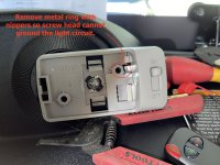
If you were succesful, you are ready to perform a small modification to the light dome ground tab ring on the inside of the fixture. Take a small pair of side cutters or nippers and remove the grounding ring that the one screw head goes through and contacts the underside of the screwhead. Remember, the remote module controls the dome light switch via the ground circuit, not the positive circuit. Leaving the ground ring in would defeat the remote control modules switching ability.

IMG_9538.JPG
Now you are ready to re-install your dome light switch.

IMG_9540.JPG

IMG_9543.JPG

Do a quick test with your KEYCHAIN FOB controller. It should be able to turn your dome light OFF and ON from at least 60' away from your RTV. Leave the on/off switch on your light dome to the ON position. Now, on those dark nights, you don't have to fumble around in the dark to find the door, you can push the button on your Key FOB and have the interior dome light come on up to 60' away. I know I will enjoy this feature.

I have added the installation sheet from the manufacturer. I don't think it is copy-righted. If the admin determines it is, I will take it down.

Scan 2.jpeg
 
Just a thought, has anyone tried a magnetic reed switch? The base would be mounted on the frame of the cab and the magnet part would be mounted on the door. That way, you are not messing with your door seals or weather strips. I pickup my new RTV-x1100C this coming week and I am going to install this on the drivers door for the dome light.
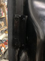
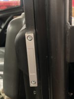
Even though my mechanical spring switch has worked well, I have found it even more difficult to close the driver's door with the spring resistance adding to the tight cab problem! If I didn't get the door completely closed the light would stay on. The time out feature has helped, but it still bothered me every time I would drive to a work site and not fully close the door. So, I decided to try a reed switch and this works well. Thank you Smilingreen for the suggestion! Now, even if the door is only slightly closed the light goes out. No more slamming the door even though I am just parked for work . The switch is in the same place as the spring mechanical switch - right above the latch. I molded some HDPE to fit the contours on the door and mounted it to the door panel and the magnet part of the switch is screwed into the HDPE. The switch part is just screwed into the plastic panel above the latch. So far so good!
 

Attachments

  • IMG_1213.JPG
    IMG_1213.JPG
    1.6 MB · Views: 5
  • IMG_1214.JPG
    IMG_1214.JPG
    1.6 MB · Views: 5
Even though my mechanical spring switch has worked well, I have found it even more difficult to close the driver's door with the spring resistance adding to the tight cab problem! If I didn't get the door completely closed the light would stay on. The time out feature has helped, but it still bothered me every time I would drive to a work site and not fully close the door. So, I decided to try a reed switch and this works well. Thank you Smilingreen for the suggestion! Now, even if the door is only slightly closed the light goes out. No more slamming the door even though I am just parked for work . The switch is in the same place as the spring mechanical switch - right above the latch. I molded some HDPE to fit the contours on the door and mounted it to the door panel and the magnet part of the switch is screwed into the HDPE. The switch part is just screwed into the plastic panel above the latch. So far so good!


I'm glad I mounted my switches beside the cupholders so they still switched it off even if the door isn't closed completely.

Dave
 

Attachments

  • 20230103_164129.jpg
    20230103_164129.jpg
    6.6 MB · Views: 6
Even though my mechanical spring switch has worked well, I have found it even more difficult to close the driver's door with the spring resistance adding to the tight cab problem! If I didn't get the door completely closed the light would stay on. The time out feature has helped, but it still bothered me every time I would drive to a work site and not fully close the door. So, I decided to try a reed switch and this works well. Thank you Smilingreen for the suggestion! Now, even if the door is only slightly closed the light goes out. No more slamming the door even though I am just parked for work . The switch is in the same place as the spring mechanical switch - right above the latch. I molded some HDPE to fit the contours on the door and mounted it to the door panel and the magnet part of the switch is screwed into the HDPE. The switch part is just screwed into the plastic panel above the latch. So far so good!
Glad that worked out well for you. If my key fob remote hadn't of worked so well, I was going to do the magnetic reed switch.
 
I'm glad I mounted my switches beside the cupholders so they still switched it off even if the door isn't closed completely.

Dave
This is also true with the reed switch. The door does not need to latch to turn the light off.
 
Top