Help on Alternator Conversion JD1020

Old JD 1020

New member
The Alternator on my John Deere 1020 wore out along with the external regulator. (Replacement Alternator $175, Regulator $57) So I decided to upgrade to a GM 3 wire alternator $50 with internal regulator. Hooked up the new regulator with main hot wire from starter and regulator worked good. (14.5 volts at battery with engine running)

Problem is when I went to hook up the other two leads (post one to alternator light, Post two routed back to hot post on alternator), my alternator light stayed on with the key off and would shut off when I turned the key on?

I disconnected the indicator light & left post two routed back to hot and alternator was working fine. Then I ran a jumper wire from alternator to indicator light to make sure there was no short in the old Ind light wire, same result alt light stayed on with key off. Next I ran a jumper wire from Alternator light to ignition switch to make sure no shorts in that line (jumper from Alternator still connected), same result light stayed on.

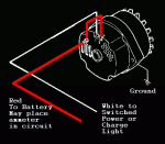
I have attached the JD wiring Diagram & the alternator wiring diagram as well.

Any thoughts out there??
 

Attachments

  • alt%20wiring.gif
    alt%20wiring.gif
    6.3 KB · Views: 60
  • wire dia004.pdf
    wire dia004.pdf
    336.9 KB · Views: 39
Not a tractor mechanic.

Hot lead to the battery from new alternator gave you 14.5 volts, great.

If it was mine, don't even hook up the other two wires. System works, when it dies 10 years down the road you'll know because it will not start.

Continue farming.

Can't read your attachment.

My 2 cents.
 
Here is what I see.

JD 1020 Alternator

B-10 (black wire) from old alternator to regulator not needed. Ground through mounting bolt of new alternator replaces this. Remove if no other wires attached to this wire.

GR-9 (green wire) from old alternator to regulator was power from the regulator to the old alternator to supply voltage for the magnetic field to generate voltage. Remove if no other wires attached to this wire.

O-7 (orange wire) from old alternator to alternator indicator lamp then to regulator not needed. Remove if no other wires attached to this wire.

PU-2 (purple wire) from key switch (marked A on key switch) to regulator is battery power to regulator that goes on to feed the field through GR-9, new alternator does not require this anymore. Remove if no other wires attached to this wire.

R-1 (red wire) is the main feed from the alternator to the battery through the starter solenoid when the engine is running. At start up the battery feeds back through the alternator connection point through the circuit breaker (fuse) to the key switch (marked B on key switch).

Key Switch
B – battery connection should always show 12 volts

S – wire to starter solenoid through what looks like a possible glow plug light, not sure

A – has PU-2 associated wires;
1 – feeds 12 volts to the regulator so it can energize the field for charging
2 – feeds the Alternator Indicator Lamp, this PU-2 is required the other PU-2 is not.

G – not used, might have been for ground???

I – has 2 wires also;
1 – feeds what looks like a gauge, possibly an amp gauge
2 – not sure where it goes???

So after removing the wires suggested, if they have no other wires connected, the only one of concern is

the PU-2 that shows a connector to another wire before it gets to the Alternator Indicator Lamp. It must

be left connected, but the B-2 (black wire) above that connection point and going to the Alternator

Indicator Lamp can be removed.

Clear as mud???

You can just unplug these wires at their connection points and tape the ends if so desired. But if you have the wire harness opened up, my preference would be to remove them.

Like I said before, indicator lamp not essential.

Hope this helps.
 
Thanks for the help, exactly my thoughts. I do like the idea of a voltage meter (analog as I am old school), because I do not have to hook it to the ignition switch and could wire it from the alternator with a simple ground. The purple wires pu2 also pigtail over to the engine light so I can at least remove half of the wires. (other half went to indicator light)

I believe my problem with the indicator light is either where it connects to the ignition switch, it is on a post with a corded resistance wire from the coil or a just a bad light.
 
If you go with the voltage meter be sure to attach to a 12 volt wire that is keyed.

In other words only has 12 volts when the key is in the ON position.

Direct power will drain the battery over time if left for any lengthy period of no use.

And yes BaiJiu the voltage meter is a better indicator of battery condition because as soon as you see 11 volts or less when the engine is running you know the charging system is going bad or your battery is done.
 
Top