Help! I spent a good portion of the afternoon hooking up the turn signal/flasher units on the 900xt. When I tried it out, the 15amp fuse for lights/flasher promptly blew. I'm sure the harness or wiring is hooked up wrong, but most of the parts of the harness seem to be foolproof ( 2prong to 2 prong plugs, etc.). However the wires to hook into the turn signal switch and the flasher switch are not specified in the instructions. I tried to get some sort of color match. Same for the parts of the harness that attach to the front blinker lamps. Any suggestions? Thanks for everyone's help.
You are using an out of date browser. It may not display this or other websites correctly.
You should upgrade or use an alternative browser.
You should upgrade or use an alternative browser.
wiring the flasher/blinker on 900xt
- Thread starter jegotcher
- Start date
Mark.Sibole
Well-known member
Trace all of your wires.If the fuse blew right away you have a ground wire hooked inth the + system someplace.The only place a ground wire should be hooked is on the light.As a flasher system wireing is all done on the + side.so you should have + voltage going from the switch to the flasher can to the light.The lights get their grounds from the frame generally.I hope im making sense to you.
Mark, Thanks for your reply. Everything is wired in a harness except for individual wires going to the turn signal switch (3 wires) and to the Flasher switch (2 wires). The individual front signals also have 2 wires going to them, 1 red, 1 black, with harness wires connecting to them (1 black, 1 green on L, 1 black, 1 ?red on R). Everything else is in a self contained plug. Do you think I've got the switches miswired?
Mark.Sibole
Well-known member
Do you have any links to the kit or images you can post for me to look at to see if I can determine the wiring for you? 3 wires to the switch should be center hot and 1 lead to each light providing power to that light depending on what position the switch is in NO ground wires on there.the wires to the flasher should be power in and the outlet of the flasher to the 3 position switch.on the front signals if only 2 wires for both of them should be 1 wire to each light and the lights should get ground from the frame or a seperate ground wire.If you have or use skype I can try to guide you there It shouldnt be all to difficult to figere it out as I have wired many turn signal setups.if you use skype let me know and ill PM you a user name or vice versa
Mark.Sibole
Well-known member
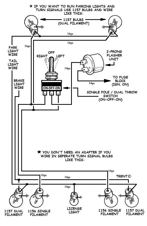
some basic wireing diagrams

Mark.Sibole
Well-known member
so your basically going from power source to the flasher to the switch to the lights as you flip the switch in 1 direction you apply voltage to that side as you flip the switch the other way you apply voltage to the other side and in the center position there is no voltage supplied to either side.
Wow, this is really great information! Thanks to all. Mark, my Kubota is up at my cabin; will stop by there tomorrow night and get some photos of the switches, etc. This is starting to make sense, the three wire switch is probably miswired. My Kubota dealer is researching this, hopefully with better pictures than the instruction sheet.
Mark.Sibole
Well-known member
Never a problem.Glad I could help.If you need more info feel free to ask.
Stuck in NJ
Member
Mark - great info - just don't forget to stress fusing the circuit. Your 2nd diagram indicates flasher gets power from 'ignition on' fuse circuit. The first drawing does not show any protection between the battery and flasher. Just a care point.